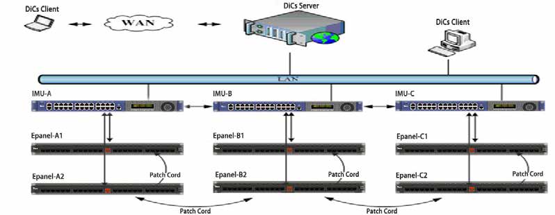
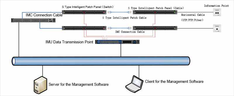
Through the deployment of intelligent hardware components and intelligent management unit throughout the network and the powerful functions of management softwares, ADDIMAX affords maximal control of network connectivity, system security and data loss, ultimately increasing network efficiency. The ADDIMAX DiCs Server manages the physical layer of the network structure through an SNMP agent that allows the management software to receive all the relevant network data. The ADDIMAX DiCs Server is connected to all the Intelligent Management Units (IMU), monitoring and scanning all the connectivity changes between any two ports of the patch panels. It collects, saves and transmits connectivity data from the IMU and updates the management software. ADDIMAX adopts distributed scanning topology to monitor network information of the copper panels or fiber panels. Each panel uses a self-scanning methodology to monitor the link status which will be sent to the DiCs Server vias the IMU for analysis.
The system is configured with simple DICS structures containing self-scanned E-panels, E-cords with 10 pin, and Intelligent Management Unit (IMU). It adopts a distributed scanning methodology to manage link information for the copper panel or fiber panel. Each panel uses its self-scanning methodology and has high speed performance.
Management software is browser based, supporting different OS3, adopting different levels of security method, remote-operation with GUI (graphical user interface). It provides port information, statistical analysis, report output for complete management analysis.
10 pin link types used for network communication.
Offering complete management solution for both copper (UTP, FTP) and fiber cabling system. It is an intelligent system that actively manages all the system equipment, monitor and record network data through LED flashing indicator, Alarm notification, and real-time display of port and outlet status.
Using two wiring methodology to map the Switch port to the patch panel port through a OLED display interface: a Inter Connect and Cross Connect design.
Allows cross-connection of patch panels, IMU with E-panels, using standard RJ45 connectors and CAT 6 UTP patch cord.
Software adopts C/S architecture for remote management. It is TCP/IP based, supporting flash browser.
Patch Panel Wiring Configurations
There are two basic configurations when it comes to connections between the horizontal cabling and active equipment such as switches. One is Cross Connect design and another is Inter Connect design.
In a Cross Connect design the switch ports are connected to an Equipment patch panel with a normal patch cord, which is made of either solid or stranded cable, depending on any channel length limitations. Patching is carried out between the equipment patch panels and the distribution patch panels by Intelligent patch cord.
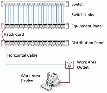
Diagram: Cross Connect Schematic
The benefit of this design is that the expensive, active equipment can be mounted in a separate, secure cabinet away from the passive patch zone, thus preventing any tampering with the active equipment. The drawbacks are that this design requires more rack space and more cabling components, with more labour required for their installation, all of which adds up to higher costs.
In an Interconnect design patching is done directly between the active equipment and the distribution patch panel(s).
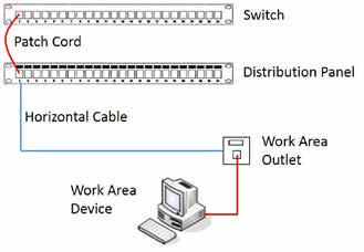
Diagram: Interconnect Schematic
This design is quicker, easier and cheaper to deploy than a Cross Connect design and requires less rack space, something that may be a consideration in Comms Rooms with limited space. It is, however, less secure as patching technicians must have access to both the active equipment and passive patch zone.
Cross Connect design is similar to the Inter Connect design except that a distribution patch panel is added. The equipment patch panel and the switch are connected through a normal patch cord. The switch port is connected to one of the equipment panel port which is then connected to the distribution panel port. The connectivity at both ends of the Intelligent patch cord is simultaneously monitored.
In this way, patch cord plugging or unplugging can be monitored to avoid the problem for the single shelf structure which can only monitor one end of the patch cord. Double shelf structure helps improve the reliability and efficiency of the network management as a whole and daily maintenance of the smart patch panels.
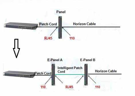
Diagram: Interconnect Configuration upgraded to Crossconnect Configuration
There are many kinds of scanning technologies for smart patch panel. Different manufacturers adopts different technologies and connection architectures. There are mainly two types: Port Type and Link Type. The Port Type comprises Port Sensing Type (such as electronic micro switch, IR sensing) and Port Identification Type (usually RFID); the Link Type comprises 9-pin Link Type and 10-pin Link Type.
The Port-Sensing Type is a communication system which includes a patch panel having connector ports on a side and a sensor module secured to patch panel side. Most of the sensor module includes IR emitters and sensors, with each emitter/sensor pair located adjacent to a respective one of the connector ports. Each emitter/sensor pair is configured to detect insertion and removal of a patch cord connector from a respective connector port. The sensor module includes a housing and a printed circuit board (PCB) secured to the housing. This design is simple. The cost is relatively low and an ordinary 8-core patch cord can be used. The disadvantage is that it is easy to cause misjudgment. Other types of patch cords or even other objects (such as fingers, crystal heads, etc.) can be mistakenly taken as the actual patch cords required to be connected to the patch panels. At the detection port, only the two ends of the patch cord can be detected. The connector cannot detect the cables of the patch cord itself. During the plugging and unplugging operation, the two ends must be inserted and removed one by one. Otherwise, inserting the same end of the two patch cords at the same time can be misjudged as the two ends of the same patch cord. Jumper relationships must be physically set up when the database is initially configured, otherwise it is difficult to locate the faulty patch cord during the operation.

Diagram:Port Sensing Type
The Port Identification Type make the contact free identification of the patch cord through RFID technology. The patch panel has an RFID reader and RF antenna associated with the connector port. Each connector of the patch cord include an RFID tag or transmitter. The RFID tags of the patch cord has the same unique identifier stored therewithin. The RFID antenna associated with a connector port emits RFID signals that cause the RFID tag of the patch cord connector to transmit its identifier. Each RF antenna detects the transmitted identifier of the RFID tag of the patch cord connector when the respective patch cord is inserted or removed. The RFID reader monitors the port status by reading and interpreting the identifier of the patch cord. When the patch cord is installed, the chip information will be set up on at both ends of the jumper to establish the jumper connection relationship. The advantage is that all the basic information about the ports, links, and patch cords can be recorded. The disadvantage is that the cost is relatively high. By installing a RFID transmitter in the connector of the patch cord, the connection at both ends of the jumper can be detected. However, the patch cord cannot be detected by itself. During plugging or unplugging, both ends of the patch cords have to be plugged or unplugged at the same time. Otherwise, inserting the same end of two patch cords at the
same time will be misjudged as the ends of the same patch cord.
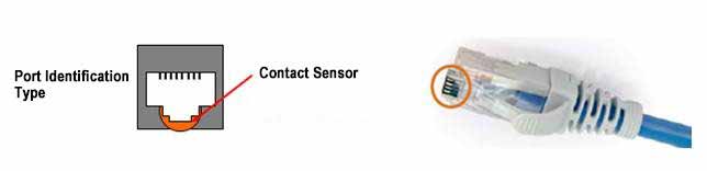
Diagram:Port Identification Type / RFID Reader
Link type mainly adopts either 9-pin or 10-pin jacks and patch cords. Through an additional pin, a detection loop is formed. The detection signal is transmitted to the scanning module through the loop and then reported to the software host. The greatest advantage of the Link Type is real-time online monitoring. Through the comparison and detection of the database, the patch cord connection can automatically be identified and corresponding alarms can be initiated under any circumstances. Patch cord connection can be done in batch at the same time; all the instructions are made through the LED lights to ensure no wrong connection is made at the port. When a batch patching is made, a physical patch connection is performed and then configured in the software platform to confirm all the patching connection. In addition, the smart patch cord itself also has certain detection function. Once the smart patch cord is broken by external force, it will break the detection circuit and generate an
alarm immediately.
The 9-pin Link Type and the 10-pin Link Type not only differ in construction, but also the scanning methodology. For the 9-pin Link Type, the 9 wire jumper cord is terminated on a non-standard 10 pin RJ45 plug. ( the neutral contact is left unterminated). For the 10-pin Link Type, the 10 wire jumper cord is terminated on a standard RJ45 plug, applying 2 probes for detection at the 0th Pin and 9th Pin positions. The corresponding RJ45 module also incorporates 2 corresponding pins. The 9-pin Link Type adopts the single-chip serial scanning method, doing scanning one by one for the patch panel port. So, the scanning time is longer, taking around several minutes for each scanning. The 10-pin Link Type adopts the double-chip parallel scanning method, supporting 24 channels. As the scanning
is done at the same time, the scanning time is much shorter and takes only a few seconds.
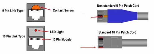
Diagram: Link Type
There are three main types of equipments, namely, Intelligent Management Unit (IMU), Intelligent Patch Panel (equipped with RJ45 keystone jacks or fiber adapters), and Intelligent 10 pin Patch Cord (copper or fiber).
The system offers a simple, straightforward way to manage network changes. It provides real-time network documentation with alerts for faults or unplanned changes to ports.
• Receive and maintain accurate, up-to-date network documentation
• Identify and diagnose problems faster, reducing downtime and risk of human error
• Assist technicians through changes and troubleshooting by managing work orders,
• logging events, and creating visual network topologies
• Help meet regulations from Sarbanes-Oxley, HIPAA, and others through detailed
• network documentation and port security
• Eliminate risk of inadvertent access to sensitive data, with the ability to lock in
• patch cords and lock out unused ports
• Easily access program software on a web browser over PCs, laptops, tablets,
• or smartphones
• Upgrade existing Leviton patch panels and enclosures to become
• Intact Intelligent panels
• Identify the physical location of active equipment connected to the network for improved asset management