IMU is the only active equipment of Distributed Intelligent Cabling System (DICS), which collects the data from the patch panel and upload them to System Server. The IMU are connected to the Smart Patch Panels with Smart Patch Cords. When IMU captures all the data from the connected Smart Patch Panels, it captures the data and uploads it to the Server for system analysis. A single IMU device can support 24 patch panels, or it can be cascaded with other IMUs through dedicated ports and CON ports. The device provides an OLED display for system information and a rotary button for on-site operation. Acting as the management center for each wiring device, IMU provides an OLED display for system information and a knob keyboard for operation in the equipment room. A 100BaseT Ethernet port is provided for connecting to a LAN. The IMU are mounted in various sites to report panel connectivity information to the Server, which contains the SNMP agent.
• Alert on unauthorized changes and provide system status information to users
• Real time tracking of changes to physical layer connection
• Accurate documentation of the end to end connectivity between networked devices
• Tracking of physical locations of IP end points
• Initial configuration of the patch panels via the built-in Web Server
• 24 standard RJ45 ports: 1~16 ports are independent working ports; 17~24 ports are working ports that can be connected with patch panels, and can also be used to cascade with other devices.
• Support Web-Server setting, which includes setting up IP address, setting up system information, wiring closet cabinet information and patch panel information through the Web-Server.
• Provide an OLED screen to display the LOGO, the IMU’s IP address, IMU ID rear port connection status, alarm information, and patch panel connection status.
• In both English and Chinese version, OLED screen interface can display real time Information or progress bar regarding different link status.
• Two CON ports are provided ; one is the management port and another is the cascade port.
• Provides a rotating flywheel button to operate the system
• Provide a knob keyboard for data input
• Provide 100BaseT Ethernet interface for connecting to the network
After starting up, IMU will show the working mode in the OLED screen display (as shown in the figure). If there is 5 minute idle, the OLED will go into the power-saving sleep mode automatically (No display). Pressing the rotary button in the power-saving mode will end the sleep, and the OLED will get back into the working mode with the display interface.
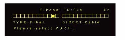
The 24 boxes represent the 24 ports of the intelligent patch panel, and the solid square in the middle indicates that the corresponding intelligent patch panel port has been connected through the intelligent patch cord to the other intelligent patch panel ports ; otherwise it means that there is no connection. The IP and ID represent the IP address and ID information of the current IMU respectively.
Rotate the button to select and connect all the intelligent patch panels of IMU. When any one of the intelligent patch panels is selected, the indicator on the right side will continue to flash. Press the rotary button to show the status display interface (as shown).
Display Intelligent patch panel information
• TYPE- Intelligent Patch Panel type
• Fiber: Fiber Patch Panel
• UTP: Unshielded Patch Panel
• STP: Shielded Patch Panel
• KEYSTONE :Keystone Patch Panel
• DIRECT :Connection direction of Intelligent Patch Panel
• CABLE: Patch panel connected with the Information Point (Indicator at the right side of intelligent patch panel is always green.)
• SWITCH: Patch panel connected with Switch Port (Indicator at the right side of intelligent patch panel is always red.)
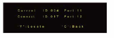
Rotate the button to select and connect all the intelligent patch panel ports of IMU. When any port is selected, the corresponding indicator will continue to flash. If the selected port has already been connected to other port, press the knob button and which will show the following display interface ; the port and its connected port will continue to flash at the same time.
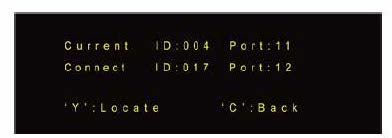
• Current - The ID information of the current port
• Connect- The ID information of the other port to which the current port is connected.
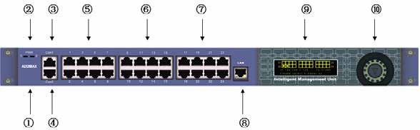
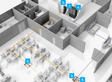
Schematic Diagram
① LOGO
② LED
Red :Power
Green :Work status
③ IMU Connection to higher authorities
④ IMU Console ports
⑤⑥ IMU and E-panels Connection Ports
⑦ IMU Connection to lower ports
⑧ IMU network port
⑨ OELD Display
⑩ spin button